


Dam Safety
Ground Penetrating Radar
Ground Penetrating Radar (GPR): How It Works, Where It's Used, and What It Can't Do
Published 2 Feb 2026Updated 2 Jun 2026101 min read
A construction crew is about to drill through a reinforced concrete slab. Nobody has seen the original drawings, and the drawings that do exist are thirty years old. One wrong hole and they hit a post-tension tendon. A GPR scan done two hours earlier would have shown exactly where every tendon runs.
That is Ground Penetrating Radar in one sentence: it shows you what is hidden before you commit to something you cannot undo.
GPR has been around long enough now that it is a standard item in the toolkit of most serious investigation teams, used for everything from mapping buried utilities in congested city corridors to assessing dam integrity, metro tunnel linings, and pavement conditions at highway speeds. Engineers in India and globally have adopted it across infrastructure, construction, geotechnical work, and archaeology.
But GPR is also one of the most misunderstood geophysical methods. Bad survey planning, wrong antenna selection, and overconfident interpretation lead to failed surveys far more often than the technology itself does. This guide covers everything you need to know, including how GPR works, what it is genuinely good at, and where it will let you down.
What is Ground Penetrating Radar (GPR)?
Ground Penetrating Radar (GPR) is a high-frequency electromagnetic geophysical method used to image subsurface features, objects, and layer boundaries without drilling or excavation.
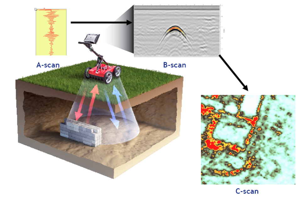
A GPR system transmits short pulses of electromagnetic energy into the ground through a transmitting antenna. When those waves hit a boundary between materials with different electrical properties (such as concrete meeting a void, or soil meeting a steel pipe), part of the energy reflects back to the surface. A receiving antenna records those reflections. The result is a continuous cross-sectional image of what lies beneath, called a radargram.
Unlike a borehole, which tells you what exists at a single point, a GPR survey gives you a continuous profile along a line, or a full 3D volume when survey lines are collected in a grid pattern.
How GPR works: the physics in plain terms
The underlying physics is not complicated, even if the interpretation sometimes is.
Dielectric contrast drives reflections. Every material has a dielectric permittivity (essentially, a measure of how electromagnetic energy moves through it). When a GPR wave crosses from one material into another with a different permittivity, some energy reflects back and some continues deeper. The bigger the contrast, the stronger the reflection. A steel rebar in concrete creates a strong reflection. A gradual change in soil moisture creates a weak one.
Travel time converts to depth. The GPR system measures the two-way travel time of each reflected pulse, which is the time it takes the wave to travel down, reflect off a target, and return to the surface. By knowing (or estimating) how fast the wave travels through the material, the system converts time to depth.
Velocity determines depth accuracy. Electromagnetic wave velocity varies significantly between materials. In dry sand it is roughly 15 cm/ns; in saturated clay it can drop to 6 cm/ns or less. Getting velocity wrong means getting depth wrong. This is why careful velocity analysis using hyperbola fitting, CMP surveys, or borehole calibration matters so much in practice.
Some examples of contrasts that produce detectable GPR reflections:
- Concrete to air void
- Dry soil to moist soil
- Sand to clay layer
- Soil to metallic utility pipe
- Rock to fracture or cavity
- Concrete to reinforcing steel
Main components of a GPR system
A GPR system has five core elements. Understanding each one helps you plan surveys intelligently and avoid common mistakes.
The control unit manages data acquisition, timing, and storage. It is the brain of the system.
The antenna does the actual transmitting and receiving of electromagnetic pulses. Antenna frequency determines both the depth you can reach and the resolution you get. More on this below. Some systems use a single antenna for both transmitting and receiving; others use a separate transmitter and receiver at a fixed spacing.
The positioning system records where each measurement was taken. This can be as simple as a wheel encoder on a cart (giving distance along a profile) or as precise as a differential GPS or robotic total station when accurate spatial coordinates are needed.
Data acquisition software records the radargrams in the field and displays them in real time, allowing the operator to monitor data quality during collection.
Processing and interpretation software is used after fieldwork to clean, filter, migrate, and visualize the data. This step is not optional. Raw GPR data rarely gives a clear picture without processing.
GPR antenna frequency: the most important decision you will make
Antenna frequency is probably the single most critical choice in any GPR survey. Get it wrong and you either have no depth, no resolution, or both.
The relationship is a trade-off: higher frequency gives better resolution but shallower depth, while lower frequency gives greater depth but lower resolution.
Frequency range | Typical penetration depth | Resolution | Primary applications |
25–200 MHz | Several metres to tens of metres | Low to moderate | Deep geology, tunnel surveys, dam investigations, large cavity detection |
250–900 MHz | 1–8 metres | Moderate to high | Utility mapping, pavement surveys, shallow geotechnical work, forensic investigations |
1 GHz–2.6 GHz+ | A few centimetres to ~1 metre | Very high | Concrete scanning, rebar mapping, bridge deck assessment, slab thickness |
One practical note: published penetration depths assume reasonably resistive ground. In high-conductivity environments (wet clay, saline soil, heavily contaminated ground), even a low-frequency antenna may only achieve a fraction of its rated depth. Always assess ground conditions before committing to a survey design.
GPR applications: what it is actually used for
GPR has an unusually broad range of applications across industries. Below are the most common ones, with notes on how the technology is applied in each case.
Utility detection and Subsurface Utility Engineering (SUE)
Locating buried utilities (water mains, sewer lines, telecom cables, electrical conduits, fibre optic networks, and abandoned pipes) is one of GPR's most common and commercially important uses.
In densely developed urban areas, utility records are often incomplete, out of date, or outright wrong. Hitting an unmarked high-voltage cable or a pressurised water main during excavation is not just costly. It is dangerous. GPR provides a non-destructive way to map what is actually in the ground before any digging begins, and it forms a core part of modern Subsurface Utility Engineering (SUE) practice.
Pavement and highway investigations
Road agencies and contractors use GPR for pavement layer thickness estimation, detection of moisture damage and stripping in asphalt, void detection beneath pavements, and network-level condition surveys. Vehicle-mounted systems can collect data at highway speeds, covering long stretches without lane closures or traffic management costs.
Airport runway and taxiway investigations are also a well-established application, where GPR helps assess structural integrity without interrupting flight operations.
Concrete and structural inspection
High-frequency GPR (1 GHz and above) is used extensively for locating reinforcing bars and their depth cover, post-tension tendon mapping before coring or drilling, void detection within concrete elements, slab thickness measurement, bridge deck condition assessment, and tunnel lining surveys.
The technique is fully non-destructive and can be carried out on live structures without taking them out of service. In renovation and retrofitting work, it has largely replaced the old practice of drilling exploratory holes.
Dam safety investigations
GPR contributes to dam safety assessment in several ways: evaluating concrete integrity in dam bodies and spillways, identifying voids and delamination, mapping seepage-related deterioration, and assessing gallery conditions. In India, dam safety legislation has increased the demand for systematic, non-invasive inspection methods, and GPR is increasingly part of integrated dam health monitoring programmes alongside Electrical Resistivity Imaging and Seismic Tomography.
Tunnel investigations
In metro rail, road tunnels, and hydropower tunnels, GPR is used to assess tunnel lining condition, detect voids behind the lining, identify groundwater ingress zones, and measure lining thickness. Vehicle-mounted and air-coupled systems allow rapid inspection of long tunnel sections, which is increasingly standard practice in large tunnel management programmes.
Archaeology and heritage investigations
Archaeologists use GPR to locate buried foundations, walls, chambers, tombs, and settlement remains before any excavation. The method's non-invasive nature makes it well suited to heritage sites where ground disturbance must be minimised. 3D GPR surveys have mapped the footprints of buried structures including walls, chambers, and pathways in days, where conventional excavation would have taken years and destroyed what it uncovered.
Environmental and geological studies
Applications in this domain include landfill boundary mapping, contamination plume investigation, sinkhole and cavity detection, glacier studies, groundwater investigation, and stratigraphic mapping. Low-frequency systems are used for the deeper geological work; medium-frequency systems cover most shallow environmental applications.
Advantages of GPR
A few things stand out when you compare GPR to conventional investigation methods.
There is no drilling, no excavation, and no disruption to the surface or the structure being investigated. It produces continuous subsurface profiles rather than isolated point data from boreholes. A single scan line tells you more than several cores placed along the same path. Experienced teams cover large areas in a single day, and vehicle-mounted systems can survey kilometres of road or tunnel in hours.
Resolution is good. With the right antenna, GPR can detect targets as small as a few centimetres. Results are available in real time in the field, so anomalies can be flagged immediately and the survey adjusted accordingly. And unlike some geophysical methods, GPR works effectively both on the ground surface and on the surface of structures like bridge decks, retaining walls, and tunnel linings.
For urban infrastructure work specifically, the ability to survey without traffic disruption is a practical advantage that is hard to overstate.
Limitations of GPR: what it cannot do
Being clear about GPR's limitations is just as important as understanding its strengths. Surveys fail when clients or contractors expect the technology to perform beyond what physics allows.
Clay and saline soils are the biggest constraint. Electrically conductive materials absorb electromagnetic energy rapidly. In clay-rich or saline ground, penetration depth can drop to almost nothing (sometimes less than half a metre) regardless of antenna frequency. Dry sandy soils offer excellent penetration; wet, clayey soils often do not. Assessing ground conductivity before a survey is not optional.
Interpretation requires expertise. A GPR radargram is not a photograph. Reflections can come from geology, utilities, moisture variations, surface objects, signal multiples, or electronic noise. Without proper training and experience, misinterpretation is common. The consequences in an engineering context can be serious.
Depth penetration varies dramatically. The same antenna that reaches 8 metres in dry sand might only reach 1 metre in saturated clay. Clients and project managers need to understand this variability and factor it into survey planning.
Metallic clutter in urban environments creates complex overlapping reflections that can mask the targets you are actually looking for. In some congested urban areas, electromagnetic interference from infrastructure adds to this problem.
Velocity estimation errors translate directly into depth errors. If the assumed wave velocity is 10% wrong, your depth estimates are 10% wrong. For targets at 3 metres depth, that is a 30 cm error, which matters if you are trying to establish utility clearance or concrete cover.
GPR is a powerful tool. It is not a universal one.
Why data processing is not an afterthought
Raw GPR data almost always contains noise, ringing, background clutter, and hyperbolic diffractions that obscure real targets. A skilled processor applies a sequence of steps to bring the meaningful information forward.
Standard processing typically includes time-zero correction, dewow filtering, bandpass filtering, background removal, gain application, and topographic correction. Migration (the process of collapsing hyperbolic reflections back to their true point positions) is often critical for accurate interpretation, especially in complex environments. For 3D surveys, horizontal time slices and volume rendering reveal spatial patterns that are invisible in individual profiles.
The difference between raw and processed data can be dramatic. Treating processing as a minor step or skipping it entirely is one of the most common reasons a technically sound survey produces an uninterpretable result.
GPR works best alongside other methods
One of the recurring mistakes in site investigation is over-relying on a single technique. GPR is not exempt from this.
In geotechnical and infrastructure investigations, GPR data becomes significantly more reliable when it is combined with complementary methods, including Electrical Resistivity Imaging for broader groundwater and stratigraphy context, MASW or Seismic Refraction for layer velocity and stiffness characterisation, boreholes for direct verification of interpreted boundaries, and CCTV for pipe condition assessment.
Integrated interpretation reduces uncertainty. It also exposes cases where GPR alone would have led to the wrong conclusion. A strong reflection interpreted as a buried utility can turn out to be a shallow rock contact, confirmed only by a single calibration borehole.
Where GPR technology is going
Several developments are reshaping what GPR surveys can deliver.
Multi-channel array systems (essentially multiple antennas mounted on a single platform) are making 3D surveys much faster and cheaper than they were a decade ago. AI-assisted interpretation is beginning to reduce the skill threshold for routine applications like rebar detection and utility mapping, though complex geological interpretation still demands experienced human judgment. Drone-mounted GPR is opening up access to difficult terrain and large structures that are impractical to survey on foot or with a vehicle. Real-time 3D imaging and cloud-based processing are shortening the gap between field acquisition and deliverable.
Integration with GIS and BIM platforms is also maturing, and GPR results can increasingly feed directly into the digital models that infrastructure owners use to manage assets over time. As infrastructure monitoring programmes expand globally and smart city development accelerates, the demand for rapid, non-invasive subsurface data is only going in one direction.
Learn GPR with AF Academy
Understanding GPR in theory is useful. Knowing how to apply it in the field, covering how to design a survey, select the right antenna, process data correctly, and interpret results under real-world conditions, is what makes the difference on an actual project.
AF Academy offers structured training programmes specifically designed for engineers, geophysicists, and infrastructure professionals working with near-surface technologies:
- 3-Month Online Course on Ground Penetrating Radar covering fundamentals through to field application
- Advanced Online Course on Ground Penetrating Radar covering complex applications, multi-method integration, and case studies
- Advanced GPR Data Processing Course covering processing workflows, migration, 3D visualisation, and interpretation
These programmes are built around real project experience, not just theory. If you are commissioning GPR surveys, managing investigation programmes, or actively working with GPR data, they are designed to close the gap between what the textbooks say and what happens in the field.
Conclusion
GPR is genuinely useful. Fast, non-invasive, and continuous, it provides subsurface information that would otherwise take weeks of drilling and significant ground disruption to obtain.
But the surveys that go wrong (and there are plenty of them) almost always trace back to avoidable decisions: the wrong antenna for the ground conditions, inadequate processing, interpretation by someone without sufficient field experience, or the assumption that GPR alone can answer a question that needs two or three methods to solve reliably.
For anyone working in construction, roads, dams, tunnelling, or infrastructure management, knowing what GPR can and cannot do is practical knowledge. The more uncertain the subsurface conditions, the more it matters to get the survey right.
Common questions
FAQ : Ground Penetrating Radar (GPR): How It Works, Where It's Used, and What It Can't Do
It depends entirely on ground conditions. In dry, resistive materials like sand or granite, low-frequency GPR systems (25–100 MHz) can reach tens of metres. In conductive materials like saturated clay, depth may be limited to less than a metre regardless of frequency. There is no single answer. Depth is a function of ground conductivity, antenna frequency, and target contrast.
Tags
- GPR Survey
- GPR Applications
- GPR Antenna Frequency
- Subsurface Imaging
- Non-Destructive Testing
- Utility Detection
- Concrete Scanning
- GPR Limitations
Read next